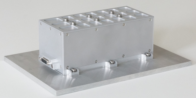
Battery BP3-SN

Features

- The battery contains LiFePO4 cells, one of the safest lithium based technologies. The cells have a high cycle life which is crucial for an acceptable mission duration. Typically they still have 80 % of their initial capacity after more than 5000 cycles with full discharge depth (100 % DOD) and a discharge current of 2 A. When shallow cycles are applied, the cycle life can be scaled according to the DOD, e.g. 50 000 cycles with 10 % DOD.

- The cells as well as the robust top balancing electronics have been verified in orbit in the past. On top of that, they have passed the total dose qualification for the space radiation environment. The five BP3-SN versions have also been qualified in the categories vibration and shock and thermal vacuum. In addition, every manufactured unit goes through an acceptance-level vibration test and functional verification tests (details on product testing are described here).

- The battery voltage can be taylored according to mission needs (from 9.9 V to 23.1 V nominal, i.e. 3 to 7 cells in series) with only minimal adaptations of the manufacturing process. Many components are the same for all voltage versions because all have three parallel strings and therefore the same width. This means that the capacity in Ah is also fixed, but for higher capacities the spacecraft can be fitted with more than one battery (a single PCU can handle several batteries).

- The battery design offers good testability, e.g. for extensive health checks after acceptance tests. All regulator circuits can be accessed for testing just by removing the bottom cover (the PCB features dedicated test points). For mechanical inspection even a complete disassembly is possible.
Specifications
- Operating Temperature
- -25 to 50 °C
- Maximum Continous Discharge Current (ICD_MAX)
- 10 A
- Capacity
- 6.6 Ah
- Cell Impedance
- 8 mΩ
- Nominal Voltage (UNOM)
- N x 3.3 V
- End Of Discharge Voltage (UEOD)
- N x 2.8 V
- Dimensions (L x W x H)
- (N x 28 mm + 40 mm) x 128 mm x 94 mm
- Mass
- N x 0.42 kg + 0.25 kg
- N = number of cells per string
Example: The BP3-S5 (5 cells in series) has a nominal voltage of 16.5 V, a length of 180 mm and a mass of 2.35 kg.
The specifications shown here are typical values, but they are not guaranteed and subject to change without notice. The performance depends strongly on the usage conditions.
Additional Remarks
The BP3-SN can be included "stand-alone" in your project, i.e. without one of our PCUs. As simple robust top balancing system it will work with any PCU that does not draw more than the specified ICD_MAX and can protect it from discharging beyond UEOD.
The battery by itself can deal with the cell failure mode increased impedance / open cell, in this case the capacity of one string is lost, but the battery stays operational. When combined with our PCU-SB7, the cell failure mode increased self discharge / short cell can also be contained through the concept of redundant Power Groups (which is introduced below in the PCUs feature list). This is one reason why we recommend to use these products together. Another reason is the fuse design of the PCU-SB7 which is especially fit for the low-impedance LiFePO4 cells that are used in the battery.
But please note that a premature cell failure is a very unlikely event (if the temperature and SOC are kept within the specified limits at all times), so the stand-alone use remains a viable option.
Power Control Unit PCU-SB7

Features

- This PCU consists of seven standard building block types: Controller, Power Group Interface (PGI), Fuse, DCDC, Delatch Fuse (DL) and two types of switches.
The core of every PCU-SB7 is a single Controller block. Then, depending on the number of devices that have to be controlled, multiple instances of the other types are added to form a complete PCU architecture (details on the building blocks and an architecture example are described here). 
- All standard building blocks have passed the total dose qualification for the space radiation environment and most have already been verified in orbit. Although built from standard blocks, every PCU-SB7 design is ultimately a tailored design and is therefore sent through individual vibration and shock and thermal vacuum qualification tests. If a separate qualification model is used for vibration and shock testing, then the flight model only undergoes an acceptance-level vibration test and functional verification tests (details on product testing are described here).

- For many products in the smallsat domain the cumulative effect of the radiation environment in space is examined with total dose tests. At the same time, single event effects (SEE) are often ignored, even though they can end a mission much quicker. The PCU-SB7 can protect the connected devices from single event latch-ups (SEL) through its monitoring function and the dedicated Delatch Fuses (DL Blocks). Also, software hang-ups caused by single event upsets (SEU) in the devices can be resolved by the Autonomous Reset circuit (AR, located in the Controller block).

- When connected to our BP3-SN battery, this PCU can form redundant Power Groups (see also PGI block description). Through this redundancy any conceivable cell or regulator failure mode can be contained. Another redundancy feature lies in the AR-Switch block. It can be used to hold vital subsystem units in cold redundancy. In this unpowered state, the spare units are largely safe from radiation damage.
Specifications
- Operating Temperature
- -25 to 50 °C
- Communication I/F
- 2 x RS422
- Voltage Measurement Points
- Resolution
- 1 mV
- Accuracy
- ± (0.1 % + 5 mV)
- Current Measurement Points
- Resolution
- 1 mA
- Accuracy
- ± (0.2 % + 2 mA)
- Temperature Measurement Points
- Resolution
- 0.05 °C
- Accuracy
- ± 0.1 °C
- DCDC
- (Example Conf.: UIN = 23.1 V, UOUT = 5.0 V)
- Efficency
- 85 %
- Load Regulation (Sweep from 0 A to 3 A)
- 5 mV
- Load Step Recovery (1 A to 2 A with 150 mA/µs)
- < 80 µs (ΔUMAX @ 110 mV)
- Ripple Current (Peak to Peak)
- < 1 mA (BW: 20 MHz)
- Ripple Voltage (Peak to Peak)
- < 1 mV (BW: 20 MHz)
The specifications shown here are typical values, but they are not guaranteed and subject to change without notice.
Additional Remarks
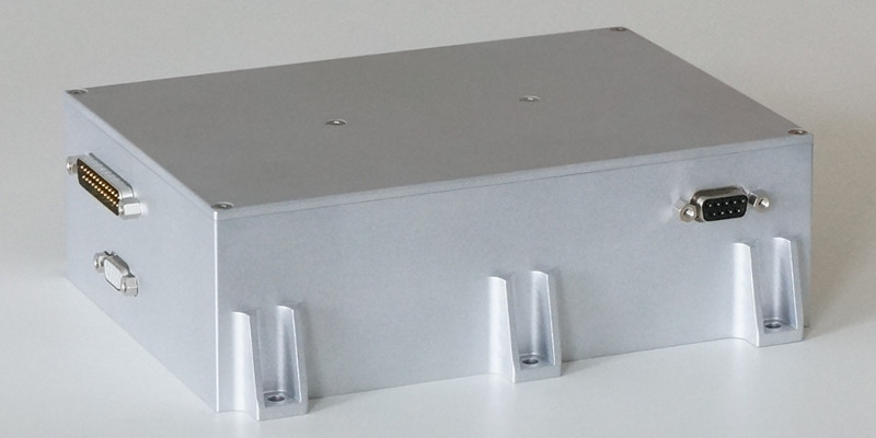
The specifications section does not contain information on maximum power output, dimensions and mass as these properties vary with the number of devices that the PCU has to control. As a rough orientation an example configuration could look like this: Controller, 3 PGIs, 8 Fuses, 4 DCDCs, 3 DLs, 4 AR-Switches, 30 Switches. The PCU-SB7 engineering model depicted above (200 mm x 150 mm x 60 mm) could accomodate such a configuration. The resulting mass would be around 1.5 kg and the total power output at 250 W.